info@strappingtoolppt.com
 +91 7604 006 074

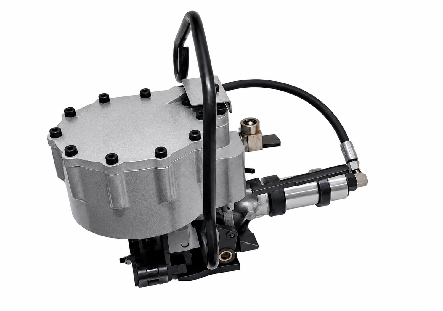
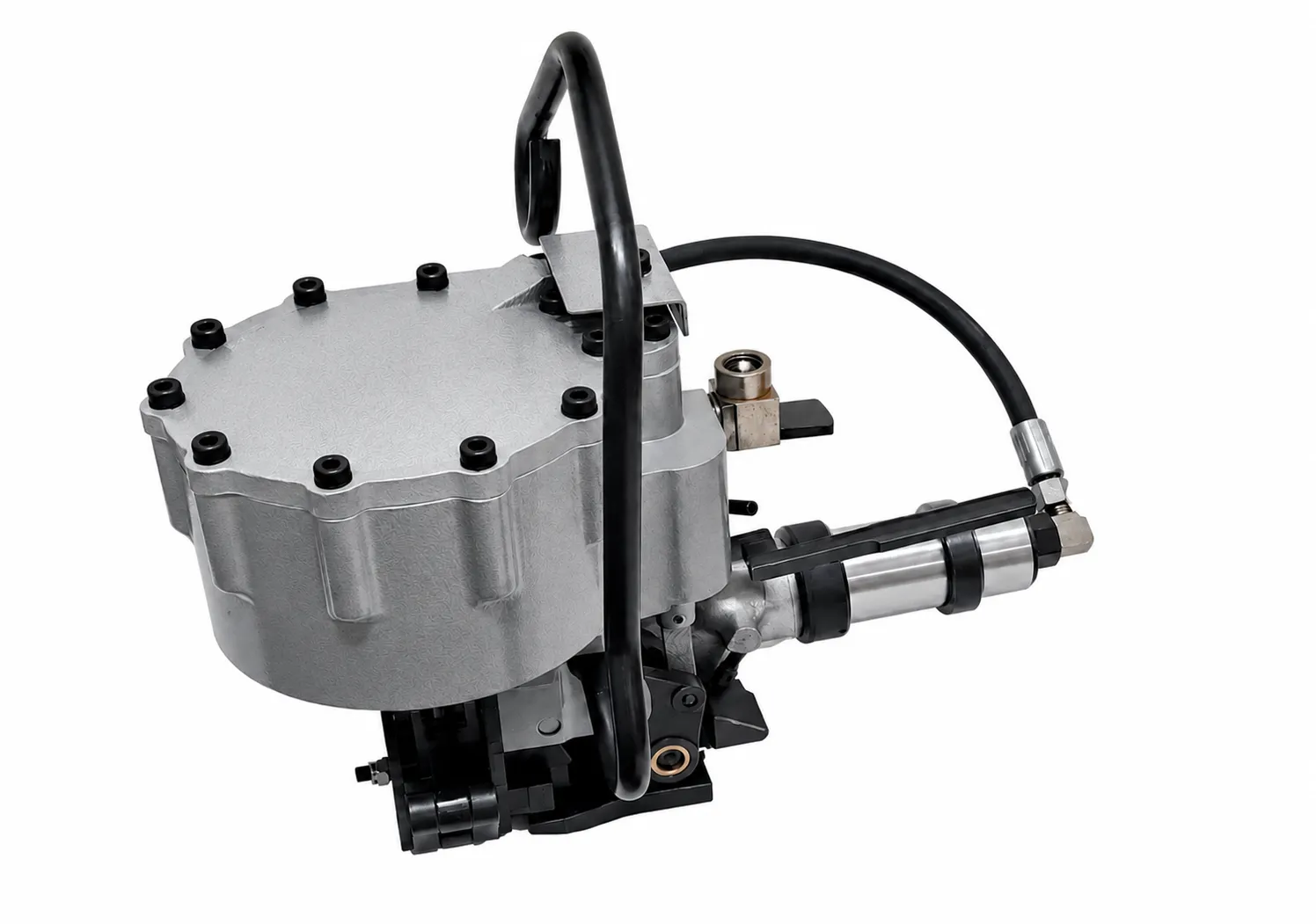
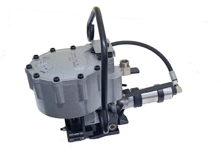
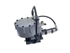
Pneumatic Steel Strapping Combination Tool
Model No.: CS-114S2
Pneumatic Steel Strapping Tool for 32 x 0.79 / 0.89 mm thick strap | Tensioning, Sealing & Cutting Machine | Heavy Duty Industrial Packaging Equipment.
Description
Upgrade your industrial packaging operations with this heavy-duty pneumatic steel strapping combination tool, designed to perform tensioning, sealing, and cutting in a single operation. This all-in-one air-powered solution improves efficiency, reduces manual effort, and minimizes the need for multiple tools—making it ideal for high-volume industrial environments.
 Download User Manual
Features:
- Heavy duty Combination Tool.
- Tensioning, Sealing & Cutting Operations done in one setting.
- Tensioner – Pusher type, Achievable tension – 725 kg / 1600 lb.
- Sealer – Double reverse notch (up cut).
- Cutter – The cutting operation done by shearing operation.
- Easy to operate & maintenance.
- Less time and man power required than individual system.
- High alloy Aluminium Cylinder body used for safety & less weight.
- Widely used in steel industries to packaging bulk materials for sheet, Coil packing & pipe bundling etc.
- Used for stationery operation, the tool may be suspended on a spring balancer using a suspension bracket.
- Inserting of the strap into the tool is easier.
Specification:
- Strap Thickness : 0.79 mm – 0.89 mm / 0.025″ – 0.035″
- Strap Width : 31.75 mm / 1.25″
- Grade : High Tensile, Painted and Waxed also can be used with M.S Strap.
- Operating Air Pressure : 6.0 kg/cm2 – 6.5 kg/cm2.
- Weight : 15.5 kg / 34.17 lb. (approx.)
- Dimension (L × W × H) : 444.5 mm × 381 mm × 266.7 mm / 17.5″ × 15″ × 10.5″
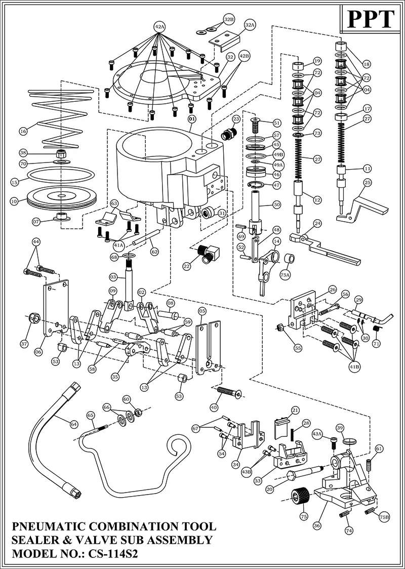
| INDEX | PART NUMBER | PART NAME | QTY. |
|---|---|---|---|
| 1 | CS34S2C01F | Cylinder Body | 1 |
| 2 | CS34S2C02B | Rear Sealer Link | 1 |
| 3 | CS34S2C03F | Ram | 1 |
| 4 | CS34S2C04F | Valve Sleeve | 6 |
| 5 | CS114S205F | Rear Side Plate | 1 |
| 6 | CS114S206F | Front Side Plate | 1 |
| 7 | CS34S2C07F | Piston Supporting Washer | 1 |
| 8 | CS34S2C08B | Ram Pin | 1 |
| 9 | CS34S2C09F | Front Sealer Link | 1 |
| 10 | CS34S2C10F | Piston | 1 |
| 11 | CS34S2C11B | Sealer Valve Stem | 1 |
| 12 | CS34S2C12B | Tensioner Valve Stem | 1 |
| 13 | CS114S213F | Jaw | 4 |
| 14 | CS34S2C14F | Outer Link | 1 |
| 15 | CS34S2C15B | O’ Ring for Piston | 1 |
| 16 | CS34S2C16B | Conical Spring (Compression) | 1 |
| 17 | CS34S2C17F | Lower Sleeve Spacer for Sealer Valve | 1 |
| 18 | CS34S2C18F | Upper Sleeve Spacer for Sealer Valve | 1 |
| 19 | CS34S2C19F | Upper Sleeve Spacer for Tensioner Valve | 1 |
| 20 | CS34S2C20F | Hex Spindle | 1 |
| 21 | CS34S2C21F | Knife (2T) | 1 |
| 22 | CS34S2C22B | 90 Degree Elbow | 1 |
| 23 | CS34S2C23B | Nipple (1/4″ BSP) | 1 |
| 24 | CS34S2C24F | Tensioner Triger Assembly (with Bush) | 1 |
| 25 | CS34S2C25F | Sealer Triger | 1 |
| 26 | CS34S2C26F | Triger Bracket | 1 |
| 27 | CS34S2C27B | Spring (O.D. – 13.3mm) | 2 |
| 28 | CS34S2C28B | Spring for Knife (O.D. – 5.5mm) | 1 |
| 29 | CS34S2C29F | Emergency Lever | 1 |
| 30 | CS34S2C30B | O’ Ring for Emergency Lever | 2 |
| 31 | CS34S2C31B | Spindle Nut | 1 |
| 32 | CS34S2C32F | Cylinder Cover | 1 |
| 32A | CS34S232AF | Air Guard | 1 |
| 32B | CS34S232BB | Washer for Air Guard | 2 |
| 33 | CS34S2033F | Knife Holder | 1 |
| 34 | CS34S2034F | Seal Stop | 1 |
| 35 | CS114S235F | Notcher | 1 |
| 36 | CS34S2C36F | Roller Frame | 1 |
| 37 | CS34S2037B | Nylock Nut for Side Plate (5/16″ BSW) | 1 |
| 38 | CS34S2038B | Ram Nut – Nylock Nut (1/2″ UNF) | 1 |
| 39 | PT77E0063F | Pressure Pad | 1 |
| 40 | CS34S2040B | Countersunk Cap Screw(5/16″BSWx 2 11/16″Long) | 1 |
| 41A | CS34SC41AB | Socket Head Cap Screw for Angle plate(M5x12Long) | 4 |
| 41B | CS34SC41BB | CSK Bolt for Triger Bracket (M6x12 Long) | 4 |
| 42A | CS34SC42AB | Round Hd. Cap Screw (for cyl. Cover) M8 x 25 Lg | 12 |
| 42B | CS34SC42BB | Round Hd. Cap Screw (for cyl. Cover) M8 x 35 Lg | 2 |
| 43A | CS34SC43AB | Round Socket Hd. Cap Screw (for Knife Holder) M6 x12 Lg. | 1 |
| 43B | CS34SC43BB | Round Socket Hd. Cap Screw (for Knife Holder) M6 x16 Lg. | 2 |
| 44 | CS34S2C44B | Round Socket Head Cap Screw (3/8″ BSW x 2″ Long) | 2 |
| 45 | CS34S2C45F | Position Piston | 1 |
| 46 | CS34S2C46B | Cylinder Plug | 1 |
| 47 | CS34S2C47B | Circlip(Internal) | 1 |
| 48 | CS34S2C48F | Position Ram Link | 1 |
| 49A | CS34SC49AB | O’ Ring for Cylinder Plug (Inner) | 1 |
| 49B | CS34SC49BB | O’ Ring for Cylinder Plug (Outer) | 1 |
| 50 | CS34S2C50F | Position Ram | 1 |
| 51 | CS34S2C51B | Counter Shank Cap Screw (5/16″ UNF x1″ Lg.) | 1 |
| 52 | CS34S2C52B | Pin for Outer Link | 1 |
| 53 | CS34S2C53F | Spacer | 2 |
| 54 | CS114S254B | Seal Stop Bolt SHC (M6 x 12Lg) | 2 |
| 55 | CS34S2C55B | 1/4″ BSW Nylock Nut | 1 |
| 56 | CS34S2C56B | Hex Headed Bolt (1/4″ x 3″ Lg) | 1 |
| 57 | CS34S2C57B | O’ Ring for Position Piston | 1 |
| 58 | CS34S2C58B | Jaw Pin | 2 |
| 59 | CS34S2C59B | Link Pin | 2 |
| 60 | CS34S2C60B | 1/2″ BSW Nylock Nut for Hanger | 1 |
| 61 | CS34S2C61B | Adjusting Screw 3/8″ UNF | 1 |
| 62 | CS34S2C62B | Pin (Dia. 3/8″x 2 9/16″ Lg) | 1 |
| 63 | CS114S263F | Angle Plate | 2 |
| 64 | CS34S2C64B | Hose Pipe (1/4″ BSP) | 1 |
| 65 | CS34S2C65F | Hanger | 1 |
| 66 | CS34S2C66B | Washer for Hanger | 2 |
| 67 | CS34S2C67B | Pin for Seal Stop | 2 |
| 68 | CS34S2C68B | Ram ‘O’ Ring | 1 |
| 69 | CS34S2C69B | C’ Pin for Position Ram | 1 |
| 70 | CS34S2C70B | Washer for Piston | 1 |
| 71 | CS34S2C71B | Spring for Emergency Lever | 1 |
| 72 | CS34S2C72B | O’ Ring for Tensioner & Sealer Valve | 8 |
| 73 | CS34S2C73F | Lower Sleeve Spacer for Tensioner Valve | 1 |
| 74 | CS34S2C74B | Gurb Screw (M5) for Pressure Pad (8Lg) | 1 |
| 75 | PT7700043F | Roller | 1 |
| 75A | CS34SC75AF | Outer Link Bush | 1 |
| 75B | CS34SC75BB | ADJUSTING SCREW LOCK (M5X12LG.) | 1 |
| SPARE PARTLIST FOR TENSIONER SUB-ASSEMBLY OF CS-114S2 | |||
| 76 | CS34S2C76F | Back Head | 1 |
| 77 | PT7700007B | Bearing No. 1 | 1 |
| 78 | PT7700008A | Endplate – 1 with locking pin – assy | 1 set |
| 79 | PT7700009F | Air Cylinder | 1 |
| 80 | PT7700010F | Rotor | 1 |
| 81 | PT7700011B | Rotor Vanes | 5 |
| 82 | PT7700018A | Endplate – 2 with locking pins – assy | 1 set |
| 83 | PT7700013B | Bearing No. 2 | 1 |
| 84 | PT7700014B | Bearing No. 3 | 2 |
| 85 | PT7700015F | 40 DP Planet Pinions (With Bush) | 2 |
| 86 | PT7700016F | 40 DP Planet Holder | 1 |
| 87 | PT7700017F | Pins for 40 DP Planets | 2 |
| 88 | PT7700012F | Retainer Washer (For 40 DP Planet Pins) | 1 |
| 89 | PT7700020F | 40 DP Internal Gear | 1 |
| 90+91 | PT7700021A | AIR MOTOR BODY WITH LOCKING PIN – ASSY | 1 |
| 92 | PT7700023F | Silencer (For Air Exhaust) | 1 |
| 93 | PT7700024B | Wire Lock (For Silencer) | 1 |
| 94 | PT7700025F | 1 Module Planet Pinions | 3 |
| 95 | PT7700076F | Locking Cap | 1 |
| 96 | PT7700028F | 1 Module Planet Holder Assy. | 1 |
| 97 | PT7700029F | 1 Module Internal Gear | 1 |
| 98 | PT7700030B | Locking Pins (For 1-M Internal Gear | 2 |
| 99 | PT7700031F | Spacer (For Bearing No.4) | 1 |
| 100 | PT7700032F | Key Bar (For Worm Shaft) | 1 |
| 101 | PT7700033B | Bearing No.4 | 1 |
| 102 | PT7700034F | Worm Shaft (3 Start) | 1 |
| 103 | PT7700035B | Bearing No.5 | 1 |
| 104 | PT7700036F | Bearing Cover – 1 (For Bearing No.5) | 1 |
| 105 | PT7700037B | Circlip (For Bearing Cover – 1) | 1 |
| 106 | PT7700038F | Worm Wheel (3 Start) | 1 |
| 107 | PT7700039B | Bearing No.6 | 2 |
| 108 | PT7700040F | Bearing Cover – 2 (For Bearing No.6) | 1 |
| 109 | PT7700041B | Circlip (For Bearing Cover – 2) | 1 |
| 110 | PT7700042F | Feed Wheel Shaft | 1 |
| 111 | PT7700065F | Housing (For Worm & Wheel) | 1 |
| 112 | PT7700067F | Bottom Cover (For Housing) | 1 |
| 113 | PT7700065B | Screws (For Bottom Cover) | 4 |
OPERATIONAL MANUAL:
- Before connecting the pneumatic hose connector with machine please check the FRL is fitted with pneumatic hose line and the hose is in safe working condition.
- Check the on line air pressure.
- Pull the strap from the coil & insert the strap in to the seal in such a way that flat surface of the seal remains facing outside the strap.
- Apply the strap around the package and bottom strap insert through the seal. Then hold the overlap portion of the straps with your left hand.
- Bend the extended strap as Hook against the seal.
- Pull out excess slack with your right hand.
- Connect the pneumatic connector with the tool. The jaws of the sealer unit will be opened & the gap between Roller & Pressure pad adjusted automatically to insert the strap into the tool.
- Insert the top strap under the feed wheel and place the seal between the jaws.
- Now press on the Tensioner Trigger for tensioning the strap.
- Then press on the sealer trigger for sealing the strap & also cut the Mother Strap.
MAINTENANCE:
DAILY INSPECTION:
- Perform a daily visual inspection for any signs of wear, damage leaks.
- Check and tighten all bolts and fasteners.
- Lubricate all moving parts before operating the machine – especially the lubricating point provided in the machine.
WEEKLY INSPECTION:
- Clean the machine to prevent dust and debris build-up.
- Check and tighten all bolts and fasteners.
- Replace any worn-out components.
MONTHLY INSPECTION:
- Inspect critical components for signs of wear and replace if necessary.
- Maintain a log of all maintenance activities.
QUARTERLY INSPECTION:
- Conduct a thorough inspection of the entire system.
- Replace any worn-out components.
ANNUAL INSPECTION:
- Perform a comprehensive overhaul of the system.
- Schedule a professional inspection and servicing.
SAFETY INSTRUCTIONS:
- Do not stand in line with the strap while it is tensioned. The strap may break.
- Do not put your fingers into the Tensioner wheel, Jaws and cutting area.
- Do not put your hand under the strap on the job while strap is tensioned.
- Only use equipment recommended for the strap. `CS-114S2’ are recommended only for 31.75 mm x 0.79 – 0.89 mm.