info@strappingtoolppt.com
 +91 7604 006 074

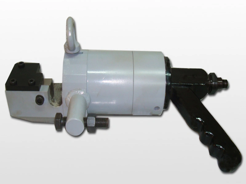
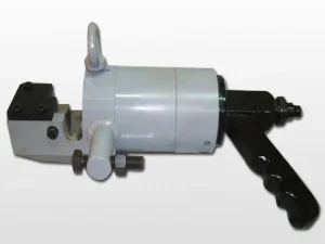
Hydraulic Sucker Rod Cutter
Model No.: HSRC-30H
PPT Hydraulic Sucker Rod Cutter HSRC-30H – 30 mm Capacity, Heavy Duty Oilfield Tool with Heat-Treated Standard Blades.
Description
The PPT Hydraulic Sucker Rod Cutter HSRC-30H is designed for heavy-duty rod cutting in oil industry applications, ensuring precision, durability, and long service life. Featuring a forged alloy steel heat-treated “C” frame and specially treated cutter blades, it delivers up to 61,367 Kgf cutting force. Lightweight yet powerful, it offers accurate alignment, easy maintenance, and compatibility with hydraulic power pack or air-hydraulic pumps.
 Download User Manual
FEATURES:
- Forged alloy steel heat treated “C” frame type cylinder body used.
- Single Acting spring return design.
- Special quality sealing for specified pressure.
- High wear resistant Moving Blade guide square bushing for accurate cutter alignment.
- Easy to operate & maintain.
- Lighter in weight than Cast Steel design.
- Unique design of blades and special steel used for longer life.
- Wide range of Hydraulic Power Pack or Air Hydraulic Pump used for different application of the user requirement.
- Single piece ram & piston design for easy maintenance.
- Suitable tool hanger fitted to positioning the tool at any angle for easy to operate.
Specification:
| Model No. | Weight | Length | Width | Height | ||||
|---|---|---|---|---|---|---|---|---|
| lb. | kg | inch | mm | inch | mm | inch | mm | |
| HSRC-30H | 121–132 | 55–60 (approx.) | 19.7 | 500 | 7.3 | 185 | 9.3 | 235 |
| Model No. | Dia. capacity (mm) | Dia. capacity (inch) | Tensile strength (kg/mm²) | Shear Strength (kg/mm²) | Cutting Force reqd. (kgf) | Cutting force generated by cutter kgf @500bar × 3.8lpm |
|---|---|---|---|---|---|---|
| HSRC-30H | Ø30.0 | Ø 1.18 | 110 | 71.5 | 50547 | 61367 |
| Ø28.6 | Ø1 ¹⁄₈ | 110 | 71.5 | 45939.2 | ||
| Ø25.4 | Ø 1.0 | 110 | 71.5 | 36234.0 | ||
| Ø22.2 | Ø ⁷⁄₈ | 110 | 71.5 | 27679.5 |
Note:
- Considering shear strength to be 65% of tensile strength.
- If you send us the specification (Tensile strength and diameter of Bar) we shall recommend the right cutter for your application.
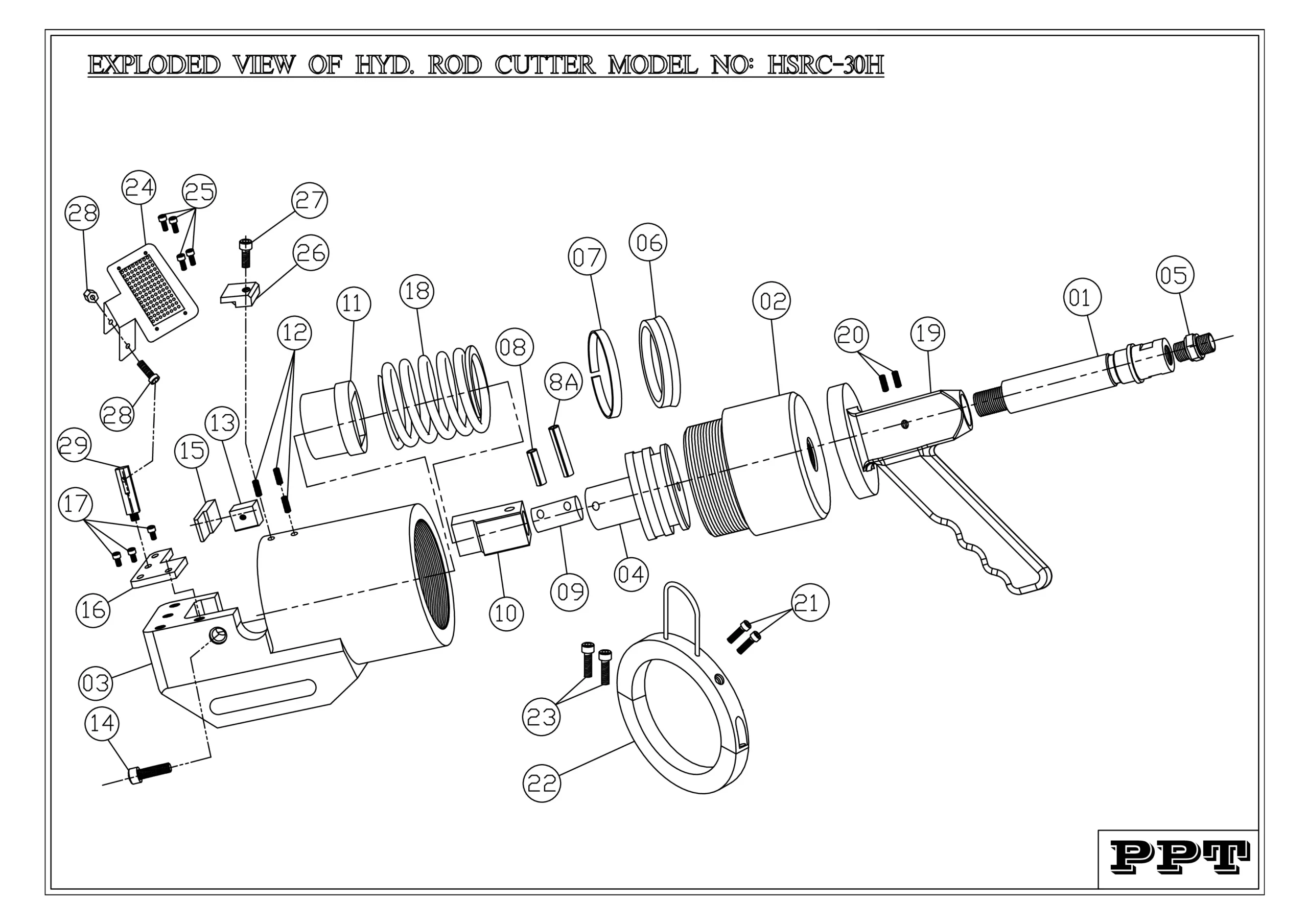
| INDEX | PART NUMBER | PART NAME | QTY. |
|---|---|---|---|
| 1 | HRCWC0001F | LONG NIPPLE | 1 |
| 2 | HRC30HS02F | CYLINDER | 1 |
| 3 | HRC30HS03F | ROD CUTTER BODY | 1 |
| 4 | HRC30HS04F | PISTON | 1 |
| 5 | HRCWC0005B | HYDRAULIC HEX SOCKET | 1 |
| 6 | HRC30HS06B | U-CUP SEAL | 1 |
| 7 | HRC30HS07B | BEARING SEAT | 1 |
| 8 | HRC30HS08B | C-PIN-2 | 1 |
| 8A | HRC30HS8AB | C-PIN-1 | 1 |
| 9 | HRCWC0009F | CONNECTOR | 1 |
| 10 | HRC30HS10F | MOVING BLADE | 1 |
| 11 | HRC30HS11F | BUSH | 1 |
| 12 | HRC30HS12B | GRUB SCREW | 2 |
| 13 | HRC30HS13F | FIXED BLADE | 1 |
| 14 | HRC30HS14B | BOLT FOR FIXED BLADE | 1 |
| 15 | HRC30HS15F | FIXED BLADE SUPPORT | 1 |
| 16 | HRC30HS16F | UPPER COVER FOR FIXED BLADE | 1 |
| 17 | HRC30HS17B | BOLTS FOR UPPER COVER | 3 |
| 18 | HRC30HS18B | SPRING | 1 |
| 19 | HRCWC0019F | HANDLE | 1 |
| 20 | HRCWC0020B | GRUB SCREW FOR HANDLE | 1 |
| 21 | HRC30HS21B | BOLT FOR HANGING RING LOCATING | 2 |
| 22 | HRC30HS22F | HANGING RING | 1 |
| 23 | HRC30HS23B | ALLEN BOLT FOR HANGING RING | 2 |
| 24 | HSRC30H24F | SAFTY GAURD | 1 |
| 25 | HSRC30H25B | BOLT FOR SAFTY GUARD WITH WASHER | 4 |
| 26 | HSRC30H26F | SAFETY GUARD LOCKING PLATE | 1 |
| 27 | HRC30HS27B | BOLT FOR LOCKING PLATE | 1 |
| 28 | HSRC30H28B | ALLEN BOLT FOR SAFETY GUARD FIXING WITH BODY | 1 |
| 29 | HSRC30H29F | HEX HOLDER FOR SAFETY GURAD | 1 |
OPERATIONAL MANUAL:
- Connect the control panel with the power supply.
- Turn on the MCB located on the control panel.
- Make sure the Red, Blue and Yellow Lights are turned on / Glowing.
- Switch on the Motor and the Solenoid in Control Panel.
- Place the Rod Securely between the Moving and Fixed Blade and make sure the Rod is aligning with the Cutting edge of the Blades and Ensure that the Full Diameter of rod is within the height of the Blades.
- Operate the Hand / Foot Switch to cut the Rod Completely and wait for the retraction of the Moving Blade. After retraction the machine is ready for the next cut.
MAINTENANCE:
DAILY INSPECTION:
- Perform a daily visual inspection for any signs of wear, damage, or leaks.
- Examine hydraulic hoses and connections for any wear or damage.
- Check and tighten all bolts and fasteners.
- Lubricate all moving parts before operating the machine.
- Clean travel area of the Moving Blade.
WEEKLY INSPECTION:
- Inspect for any hydraulic fluid leaks.
- Clean the machine to prevent dust and debris build-up.
MONTHLY INSPECTION:
- Inspect critical components for signs of wear and replace if necessary.
- Maintain a log of all maintenance activities.
- Check the Oil Levels.
QUARTERLY INSPECTION:
- Conduct a thorough inspection of the entire system.
- Replace any worn-out components.
- Clean the Strainers fitted with the Pump.
ANNUAL INSPECTION:
- Perform a comprehensive overhaul of the system.
- Schedule a professional inspection and servicing.
- Before using the Machine, read the operating instructions carefully.
- Must operate by a Trained Personnel equipped with appropriate Personal Protective Equipment (PPE).
- This Model is Suitable for certain Size of Rod and Tensile Strength. Do not ever try to cut Oversize Rod and Greater Tensile Strength.
- Ensure the work piece is placed securely Between the Moving and Fixed Blade.
- While the machine is not in use, keep the Hydraulic Power Pack switched off, so that accidental pressing of Switch cannot cause any injury.
- Before the Operation make sure to keep hands and body clear of the Blades.
- See that nobody is standing on the other end of the rod, because depending on the tensile strength of the material and flow rate of the power pack, the parted portion of the rod may shoot out at high speed causing injury.
- Check that the Balancer and Hanging arrangement is strong enough to hold the combined weight of the cutter and the job.
- During the Operation don’t open the Control panel.
- Don’t let any untrained personnel open the control panel.
- During the Operation Don’t let any Untrained and Unauthorized personnel near the machine.
- Clean the area around the equipment to prevent any hazard.
SAFETY INSTRUCTIONS: