info@strappingtoolppt.com
 +91 7604 006 074

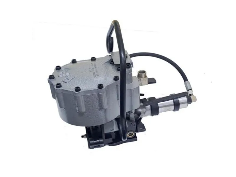
Pneumatic Steel Strapping Combination Tool
Model No.: CS-34S2
Pneumatic Steel Strapping Combination Tool for 19 x 0.79 / 0.89 mm thick strap | Heavy Duty Air Powered Tensioner, Sealer & Cutter | Pusher Type Strapping Machine | For High Tensile & M.S Steel Straps.
Description
Streamline industrial packaging with this pneumatic steel strapping combination tool, performing tensioning, sealing, and cutting in one step. Delivering up to 725 kg tension with reliable double notch sealing, it ensures secure strapping for heavy loads. Lightweight yet durable, it suits varied steel straps and is ideal for warehouses, logistics, and steel industries requiring efficient, high-volume strapping.
 Download User Manual
Features:
- Heavy duty Combination Tool.
- Tensioning, Sealing & Cutting Operations done in one setting.
- Tensioner – Pusher type, Achievable tension – 725 kg / 1600 lb.
- Sealer – Double reverse notch (up cut).
- Cutter – The cutting operation done by shearing operation.
- Easy to operate & maintenance.
- Less time and man power required than individual system.
- High alloy Aluminum Cylinder body used for safety & less weight Widely used in steel industries to packaging bulk materials for sheet, Coil packing & pipe bundling etc.
- Used for stationery operation, the tool may be suspended on a spring balancer using a suspension bracket.
- Inserting of the strap into the tool is easier.
Specification:
- Strap Thickness : 0.64 mm – 0.89 mm / 0.025″ – 0.035″
- Strap Width : 19.05 mm / ¾″
- Grade : High Tensile, Painted and Waxed also can be used with M.S Strap.
- Operating Air Pressure : 6.0 kg/cm2 – 6.5 kg/cm2.
- Weight : 15.5 kg / 34.7 lb. (approx.)
- Dimension (L x W x H) : 444.5 mm × 381 mm × 266.7 mm / 17.5″ × 15″ × 10.5″.
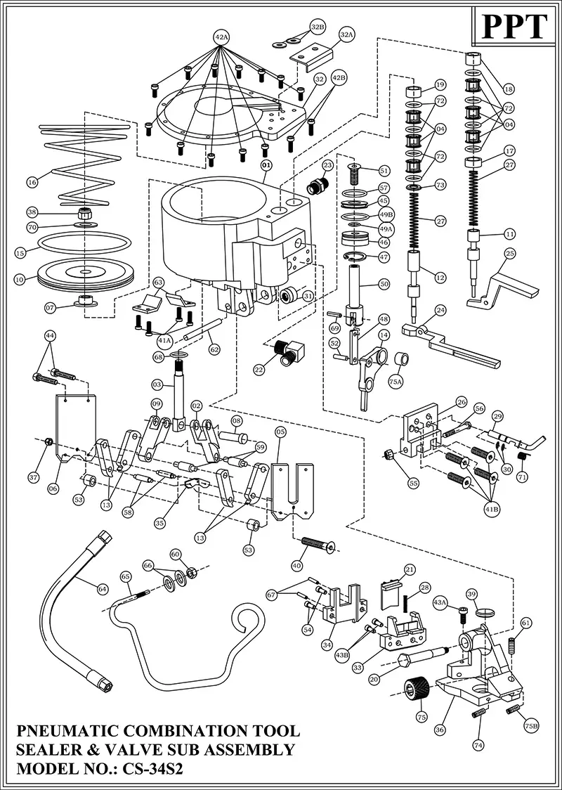
| INDEX | PART NUMBER | PART NAME | QTY. |
|---|---|---|---|
| 1 | CS34S2C01F | Cylinder Body | 1 |
| 2 | CS34S2C02B | Rear Sealer Link | 1 |
| 3 | CS34S2C03F | Ram | 1 |
| 4 | CS34S2C04F | Valve Sleeve | 6 |
| 5 | CS34S2005F | Rear Side Plate | 1 |
| 6 | CS34S2006F | Front Side Plate | 1 |
| 7 | CS34S2C07F | Piston Supporting Washer | 1 |
| 8 | CS34S2C08B | Ram Pin | 1 |
| 9 | CS34S2C09F | Front Sealer Link | 1 |
| 10 | CS34S2C10F | Piston | 1 |
| 11 | CS34S2C11B | Sealer Valve Stem | 1 |
| 12 | CS34S2C12B | Tensioner Valve Stem | 1 |
| 13 | CS34S2013F | Jaw | 4 |
| 14 | CS34S2C14F | Outer Link | 1 |
| 15 | CS34S2C15B | O’ Ring for Piston | 1 |
| 16 | CS34S2C16B | Conical Spring (Compression) | 1 |
| 17 | CS34S2C17F | Lower Sleeve Spacer for Sealer Valve | 1 |
| 18 | CS34S2C18F | Upper Sleeve Spacer for Sealer Valve | 1 |
| 19 | CS34S2C19F | Upper Sleeve Spacer for Tensioner Valve | 1 |
| 20 | CS34S2C20F | Hex Spindle | 1 |
| 21 | CS34S2C21F | Knife (2T) | 1 |
| 22 | CS34S2C22F | 90 Degree Elbow | 1 |
| 23 | CS34S2C23F | Nipple (1/4″ BSP) | 1 |
| 24 | CS34S2C24F | Tensioner Triger Assembly (with Bush) | 1 |
| 25 | CS34S2C25F | Sealer Triger | 1 |
| 26 | CS34S2C26F | Triger Bracket | 1 |
| 27 | CS34S2C27B | Spring (O.D. – 13.3mm) | 2 |
| 28 | CS34S2C28F | Spring for Knife (O.D. – 5.5mm) | 1 |
| 29 | CS34S2C29F | Emergency Lever | 1 |
| 30 | CS34S2C30B | O’ Ring for Emergency Lever | 2 |
| 31 | CS34S2C31B | Spindle Nut | 1 |
| 32 | CS34S2C32F | Cylinder Cover | 1 |
| 32A | CS34S232AF | Air Guard | 1 |
| 32B | CS34S232BB | Washer for Air Guard | 2 |
| 33 | CS34S2033F | Knife Holder | 1 |
| 34 | CS34S2034F | Seal Stop | 1 |
| 35 | CS34S2035F | Notcher | 1 |
| 36 | CS34S2036F | Roller Frame | 1 |
| 37 | CS34S2037F | Nylock Nut for Side Plate (5/16″ BSW) | 1 |
| 38 | CS34S2038F | Ram Nut – Nylock Nut (1/2″UNF) | 1 |
| 39 | PT77E0026B | Pressure Pad | 1 |
| 40 | CS34S2040B | Countersunk Cap Screw(5/16″BSWx 2 11/16″Long) | 1 |
| 41A | CS34SC41AF | Socket Head Cap Screw for Angle plate(M5x12Long) | 4 |
| 41B | CS34SC41BB | CSK Bolt for Triger Bracket (M6x12 Long) | 4 |
| 42A | CS34SC42AB | Round Hd. Cap Screw (for cyl. Cover) M8 x 25 Lg | 12 |
| 42B | CS34SC42BB | Round Hd. Cap Screw (for cyl. Cover) M8 x 35 Lg | 2 |
| 43A | CS34SC43AB | Round Socket Hd. Cap Screw (for Knife Holder) M6 x12 Lg. | 1 |
| 43B | CS34SC43BB | Round Socket Hd. Cap Screw (for Knife Holder) M6 x16 Lg. | 2 |
| 44 | CS34S2C44B | Round Socket Head Cap Screw (3/8″ BSW x 2″ Long) | 2 |
| 45 | CS34S2C45F | Position Piston | 1 |
| 46 | CS34S2C46B | Cylinder Plug | 1 |
| 47 | CS34S2C47B | Circlip(Internal) | 1 |
| 48 | CS34S2C48F | Position Ram Link | 1 |
| 49A | CS34SC49AB | O’ Ring for Cylinder Plug (Inner) | 1 |
| 49B | CS34SC49BB | O’ Ring for Cylinder Plug (Outer) | 1 |
| 50 | CS34S2C50F | Position Ram | 1 |
| 51 | CS34S2C51B | Counter Shank Cap Screw (5/16″ UNF x1″ Lg.) | 1 |
| 52 | CS34S2C52B | Pin for Outer Link | 1 |
| 53 | CS34S2C53F | Spacer | 2 |
| 54 | CS34S2054B | Seal Stop Bolt SHC (M6 x 12Lg) | 2 |
| 55 | CS34S2C55B | 1/4″ BSW Nylock Nut | 1 |
| 56 | CS34S2C56B | Hex Headed Bolt (1/4″ x 3″ Lg) | 1 |
| 57 | CS34S2C57B | O’ Ring for Position Piston | 1 |
| 58 | CS34S2C58B | Jaw Pin | 2 |
| 59 | CS34S2C59B | Link Pin | 2 |
| 60 | CS34S2C60B | 1/2″ BSW Nylock Nut for Hanger | 1 |
| 61 | CS34S2C61B | Adjusting Screw 3/8″ UNF | 1 |
| 62 | CS34S2C62B | Pin (Dia. 3/8″x 2 9/16″ Lg) | 1 |
| 63 | CS32S2063F | Angle Plate | 2 |
| 64 | CS34S2C64B | Hose Pipe (1/4″ BSP) | 1 |
| 65 | CS34S2C65F | Hanger | 1 |
| 66 | CS34S2C66B | Washer for Hanger | 2 |
| 67 | CS34S2C67B | Pin for Seal Stop | 2 |
| 68 | CS34S2C68B | Ram ‘O’ Ring | 1 |
| 69 | CS34S2C69B | C’ Pin for Position Ram | 1 |
| 70 | CS34S2C70B | Washer for Piston | 1 |
| 71 | CS34S2C71B | Spring for Emergency Lever | 1 |
| 72 | CS34S2C72B | O’ Ring for Tensioner & Sealer Valve | 8 |
| 73 | CS34S2C73F | Lower Sleeve Spacer for Tensioner Valve | 1 |
| 74 | CS34S2C74B | Gurb Screw (M5) for Pressure Pad (8Lg) | 1 |
| 75 | PT7700043F | Roller | 1 |
| 75A | CS34SC75AF | Outer Link Bush | 1 |
| 75B | CS34SC75BB | Adjusting Screw Lock (m5x12 Lg.) | 1 |
| SPARE PARTLIST FOR TENSIONER SUB-ASSEMBLY OF CS-34S2 | |||
| 76 | CS34S2C76F | Back Head | 1 |
| 77 | PT7700007F | Bearing No. 1 | 1 |
| 78 | PT7700008F | Endplate – 1 | 1 |
| 79 | PT7700009F | Air Cylinder | 1 |
| 80 | PT7700010F | Rotor | 1 |
| 81 | PT7700011B | Rotor Vanes | 5 |
| 82 | PT7700018F | Endplate – 2 | 1 |
| 83 | PT7700013B | Bearing No. 2 | 1 |
| 84 | PT7700014B | Bearing No. 3 | 2 |
| 85 | PT7700015F | 40 DP Planet Pinions (With Bush) | 2 |
| 86 | PT7700016F | 40 DP Planet Holder | 1 |
| 87 | PT7700017F | Pins for 40 DP Planets | 2 |
| 88 | PT7700012F | Retainer Washer (For 40 DP Planet Pins) | 1 |
| 89 | PT7700020F | 40 DP Internal Gear | 1 |
| 90+91 | PT7700021A | AIR MOTOR BODY WITH LOCKING PIN – ASSY | 1 |
| 92 | PT7700023F | Silencer (For Air Exhaust) | 1 |
| 93 | PT7700024B | Wire Lock (For Silencer) | 1 |
| 94 | PT7700025F | 1 Module Planet Pinions | 3 |
| 95 | PT7700076F | Locking Cap | 1 |
| 96 | PT7700028F | 1 Module Planet Holder Assy. | 1 |
| 97 | PT7700029F | 1 Module Internal Gear | 1 |
| 98 | PT7700030B | Locking Pins (For 1-M Internal Gear | 2 |
| 99 | PT7700031F | Spacer (For Bearing No.4) | 1 |
| 100 | PT7700032F | Key Bar (For Worm Shaft) | 1 |
| 101 | PT7700033B | Bearing No.4 | 1 |
| 102 | PT7700034F | Worm Shaft (3 Start) | 1 |
| 103 | PT7700035B | Bearing No.5 | 1 |
| 104 | PT7700036F | Bearing Cover – 1 (For Bearing No.5) | 1 |
| 105 | PT7700037B | Circlip (For Bearing Cover – 1) | 1 |
| 106 | PT7700038F | Worm Wheel (3 Start) | 1 |
| 107 | PT7700039B | Bearing No.6 | 2 |
| 108 | PT7700040F | Bearing Cover – 2 (For Bearing No.6) | 1 |
| 109 | PT7700041F | Circlip (For Bearing Cover – 2) | 1 |
| 110 | PT7700042F | Feed Wheel Shaft | 1 |
| 111 | PT7700065F | Housing (For Worm & Wheel) | 1 |
| 112 | PT7700067F | Bottom Cover (For Housing) | 1 |
| 113 | PT7700065B | Screws (For Bottom Cover) | 4 |
| 114 | PT7700027B | Pin (For End Plate 1 & 2 Locking) | 2 |
OPERATIONAL MANUAL:
- Before connecting the pneumatic hose connector with pneumatic combination tool, please check the FRL is fitted with pneumatic hose line and the hose is in safe working condition.
- Check the on-line air pressure.
- Pull the strap from the coil & insert the strap into the seal in such a way so that flat surface of the seal remains facing outside the strap.
- Apply the strap around the package and bottom strap insert through the seal. Then hold the overlap portion of the straps with your left hand.
- Bend the extended strap as hook against the seal.
- Pull out excess slack with your right hand.
- Connect the pneumatic connector with the tool. The jaws of the sealer unit will be opened & the gap between roller & pressure pad adjusted automatically for inserting the strap into the tool.
- Insert the top strap under the feed wheel and place the seal between the jaws.
- Press the tensioner trigger for tensioning the strap.
- Press the sealer trigger for sealing the strap & also cut the mother strap.
MAINTENANCE:
DAILY INSPECTION:
- Perform a daily visual inspection for any signs of wear, damage leaks to the pneumatic combination tool.
- Check and tighten all bolts and fasteners.
- Lubricate all moving parts before operating the pneumatic combination tool – especially the lubricating point provided in the pneumatic combination tool.
WEEKLY INSPECTION:
- Clean the pneumatic combination tool to prevent dust and debris build-up.
- Check and tighten all bolts and fasteners.
- Replace any worn-out components of the pneumatic combination tool.
MONTHLY INSPECTION:
- Inspect critical components for signs of wear and replace if necessary of the pneumatic combination tool.
- Maintain a log of all maintenance activities for the pneumatic combination tool.
QUARTERLY INSPECTION:
- Conduct a thorough inspection of the entire pneumatic combination tool.
- Replace any worn-out components of the pneumatic combination tool.
ANNUAL INSPECTION:
- Perform a comprehensive overhaul of the pneumatic combination tool.
- Schedule a professional inspection and servicing.
SAFETY INSTRUCTIONS:
- Before using the pneumatic combination tool, read the operating instructions carefully.
- Wear hand gloves, safety shoe, helmet, goggles during operation.
- Do not stand in line with the strap while it is tensioned. The strap may break.
- Do not put your fingers into the tensioner wheel, jaws and cutting area.
- Do not put your hand under the strap on the job while strap is tensioned.
- Only use equipment recommended for the strap. ‘CS-34S2’ are recommended only for 19.05 x 0.79 to 0.89 mm thick strap.