info@strappingtoolppt.com
 +91 7604 006 074

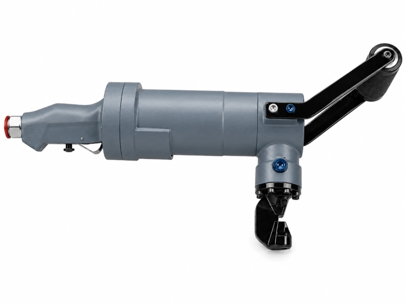
Pneumatic Sheet Nibbler
Model No.: PN-5
Pneumatic Sheet Nibbling Machine | Heavy Duty Air Powered Metal Cutter | Portable Sheet Cutting Tool for Steel & Aluminium | Industrial Nibbler up to 7 mm Capacity
Description
Pneumatic Sheet Nibbling Machine is a compressed air-powered cutting tool which cuts sheet metals cleanly without edge distortion. It uses a fast-moving Punch and Die mechanism to rapidly chip away small pieces of metal. Capable of cutting steel sheets up to 5.0 mm (400 N/mm²) and aluminium up to 7.0 mm thickness, it delivers precise and efficient performance across a variety of materials. Its lightweight and portable design ensures easy handling, while the simple operation allows even unskilled operators to use it effectively. Running on 85 psi – 100 psi air pressure with an average cutting speed of 1.4 m/min, this tool offers reliable, smooth, and maintenance-friendly performance for fabrication and sheet metal industries.
 Download User Manual
Features:
- Heavy-duty sheet Nibbling Machine
- Handy
- Easy to operate and maintain
- Un-skilled operator can run the Nibbling Machine
Specification:
| Maximum Material Thickness To Be Cut | Required Continuous Working Air Pressure |
|---|---|
| Steel up to 400 N/mm² – 5.0 mm / 0.20″ | 100 psi |
| Steel up to 600 N/mm² – 3.2 mm / 0.13″ | 90 psi |
| Steel up to 800 N/mm² – 2.5 mm / 0.10″ | 85 psi |
| Aluminium 250 N/mm² – 7.0 mm / 0.28″ | 100 psi |
- Average Cutting Speed : 1.4 m/minute (Varies with Material Sheet Thickness & Air Pressure).
- Continuous Rated Air Pressure : 6.0 Kg/Cm2 – 6.5 Kg/Cm2
- Weight : 7 Kg / 15.4 lb
- Size (L X W X H) : 500 mm x 155 mm x 240 mm / 19.7” x 6.1” x 9.5”
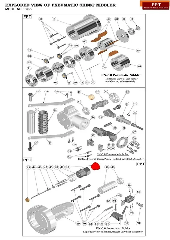
| Index No. | Part Number | Part Name | Quantity |
|---|---|---|---|
| 01 | PSNM00001F | END COVER-1 | 1 |
| 02 | PSNM00002B | BALL BEARINGS, 6003-2Z, SKF OR EQUIVALENT | 2 |
| 03 | PSNM00003F | ROTOR WITH 1.5M SUN-PINION | 1 |
| 04 | PSNM00004F | ROTOR VANES | 5 |
| 05 | PSNM00005F | AIR-CYLINDER | 1 |
| 06 | PSNM00006F | END COVER-2 | 1 |
| 07 | PSNM00007F | 1.5M INTERNAL GEAR | 1 |
| 08 | PSNM00008F | 1.5M PLANET PINIONS WITH BUSH | 3 |
| 09 | PSNM00009F | PLANET HOLDER | 1 |
| 10 | PSNM00010F | PINS FOR PLANET PINIONS | 3 |
| 11 | PSNM00011B | BALL BEARINGS, 6007-2Z, SKF OR EQUIVALENT | 2 |
| 12 | PSNM00012F | LOCATING PIN FOR MOTOR & INTERNAL GEAR | 1 |
| 13 | PSNM00013F | HOUSING FOR MOTOR & GEARING (Machining Drg.) | 1 |
| 14 | PSNM00014B | BEARING LOCKING SCREW FOR ROTOR (3/8” UNF) | 1 |
| Index No. | Part Number | Part Name | Quantity |
|---|---|---|---|
| 15 | PSNM00015B | BALL BEARINGS, EE-8, SKF OR EQUIVALENT | 1 |
| 16 | PSNM00016F | HOUSING FOR CRANK-SHAFT (MACHINING DRG.) | 1 |
| 17 | PSNM00017B | BALL BEARINGS, EE-5, SKF OR EQUIVALENT | 1 |
| 18 | PSNM00018F | CRANK SHAFT | 1 |
| 19 | PSNM00019B | NEEDLE BEARING WITH FLEXIBLE CAGE (STRIP) | 1 |
| 20 | PSNM00020F | CRANK LINK | 1 |
| 21 | PSNM00021F | PUNCH HOLDER | 1 |
| 22 | PSNM00022F | CONNECTING PIN | 1 |
| 23 | PSNM00023F | PUNCH | 1 |
| 24 | PSNM00024F | HANDLE PLATES | 2 |
| 25 | PSNM00025B | SCREWS FOR HANDLE PLATES | 4 |
| 26 | PSNM00026B | HANDLE GRIP (RUBBER) | 1 |
| 27 | PSNM00027F | HANDLE GRIP INSERT (ALUMINIUM) | 1 |
| 28 | PSNM00028B | SCREWS FOR HANDLE GRIP INSERT | 2 |
| 29 | PSNM00029F | LOCKING FLANGE | 1 |
| 30 | PSNM00030B | SCREWS FOR LOCKING FLANGE | 8 |
| 31 | PSNM00031F | ANVIL | 1 |
| 32 | PSNM00032F | GUIDE FOR PUNCH | 1 |
| 33 | PSNM00033B | SCREWS FOR GUIDE | 2 |
| 34 | PSNM00034B | SCREWS FOR DIE | 2 |
| 35 | PSNM00035F | DIE FOR 1-2mm THICK STEEL | 1 |
| 36 | PSNM00036F | DIE FOR 2-3mm THICK STEEL | 1 |
| 37 | PSNM00037F | DIE FOR 3-5mm THICK STEEL | 1 |
| 38 | PSNM00038F | DIE FOR 7mm THICK ALUMINIUM | 1 |
| 52 | PSNM00052B | CIRCLIP FOR CONNECTING PIN | 1 |
| 53 | PSNM00053B | LOCKING SCREW FOR ANVIL | 1 |
| Index No. | Part Number | Part Name | Quantity |
|---|---|---|---|
| 39 | PSNM00039F | REAR HANDLE AND TRIGGER-VALVE HOUSING | 1 |
| 40 | PSNM00040B | SHC SCREWS FOR REAR HANDLE, 2-BA x 32mm L | 6 |
| 41 | PSNM00041F | ADAPTER FOR NIPPLE | 1 |
| 42 | PSNM00042F | ADAPTOR DUST-CAP | 1 |
| 43 | PSNM00043B | VALVE SPRING | 1 |
| 44 | PSNM00044F | VALVE PIN | 1 |
| 45 | PSNM00045F | VALVE CAP | 1 |
| 46 | PSNM00046B | VALVE-PIN SPRING | 1 |
| 47 | PSNM00047B | VALVE-PIN NUT | 1 |
| 48 | PSNM00048F | SPACER | 1 |
| 49 | PSNM00049F | VALVE BODY | 1 |
| 50 | PSNM00050F | VALVE BUSH | 1 |
| 51 | PSNM00051F | TRIGGER | 1 |
| 55 | PSNM00055F | TRIGGER PIN | 1 |
| 56 | PSNM00056F | LEVER | 1 |
| 57 | PSNM00057F | LEVER PIN | 1 |
| 58 | PSNM00058F | PAWL BLOCK | 1 |
| 59 | PSNM00059B | GRUB SCREW | 4 |
| 60 | PSNM00060F | RELEASE BUTTON | 1 |
| 61 | PSNM00061F | LOCK PLATE | 1 |
| 62 | PSNM00062F | PAWL BLOCK SIDE-SPRING | 1 |
| 63 | PSNM00063F | PAWL BLOCK BOTTOM-SPRING | 1 |
OPERATIONAL MANUAL:
- Before connecting the pneumatic hose connector with the nibbling machine, ensure that the FRL is fitted with the pneumatic hose line and that the hose is in safe working condition.
- Mark the cut line on the job. Set the nibbling machine as per size and grade of the material to be cut.
- Connect the pneumatic connector with the nibbling machine and check the air line pressure.
- Let the nibbling machine run idle for a few seconds.
- To achieve proper control during cutting, hold the front and rear handle of the nibbling machine with both hands and stabilize your hands and body against the job.
- Press the trigger in a controlled manner and set the nibbling machine into the workpiece to begin cutting. As the cut progresses, keep the tool properly positioned against the job for smooth operation.
- After finishing, or when leaving the area, disconnect the tool from the air line and store it in a proper place.
SAFETY INSTRUCTIONS:
- Wear your safety shoes, gloves, goggles and helmet.
- Remove oil or grease from your hands, tools, and from the floor and area where you will be working.
- Use proper cutting tool as per type, size, and hardness of metal to be cut. Do not force the tool to do a job for which it was not designed.
- Follow the operating instructions.
- Keep the tool lubricated and clean for best and safest performance.
Related Products