info@strappingtoolppt.com
 +91 7604 006 074

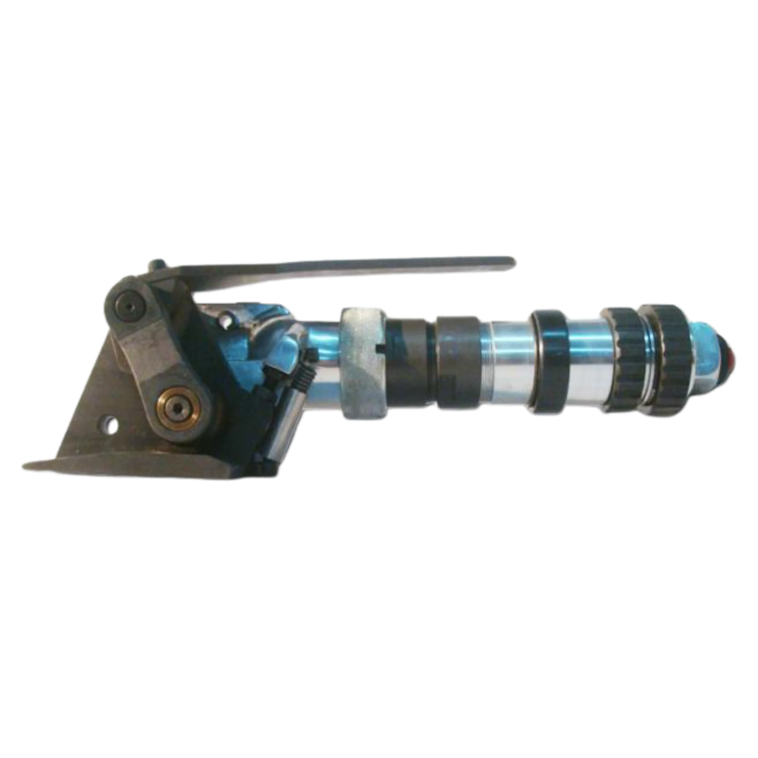
Pneumatic Steel Strap Tensioner
Model No.: T-177LHR
Pneumatic Pusher Type Steel Strap Tensioner – Heavy Duty, High Tensile, Reversible Motor, Easy Operation for Wagon Unitization & Ship Lashing.
Description
The Pneumatic Pusher Type Steel Strap Tensioner is built for heavy-duty industrial strapping applications, offering strength, reliability, and ease of use. Equipped with a reversible motor, it ensures smooth and efficient tensioning of high tensile steel straps, making it ideal for demanding tasks such as wagon unitization and ship lashing.
 Download User Manual
Features:
- Pneumatic Pusher type Steel Strap Tensioner with reversible motor.
- Suitable for high tensile strap.
- Easy to operate and maintain.
- Suitable for wagon unitization & ship lashing.
- To be used with pre-cut strap.
Specification:
- Strap Thickness : 1.27 mm / 0.05”
- Strap Width : 31.75 mm / 11/4”
- Grade : High Tensile
- Operating Air Pressure : 8.0 kg/cm2 – 10.0 kg/cm2
- Weight : 5.270 kg / 11.59 lb
- Dimension (L X W X H) : 350 mm x 110 mm x 115 mm / 13.78” x 4.33” x 4.53”
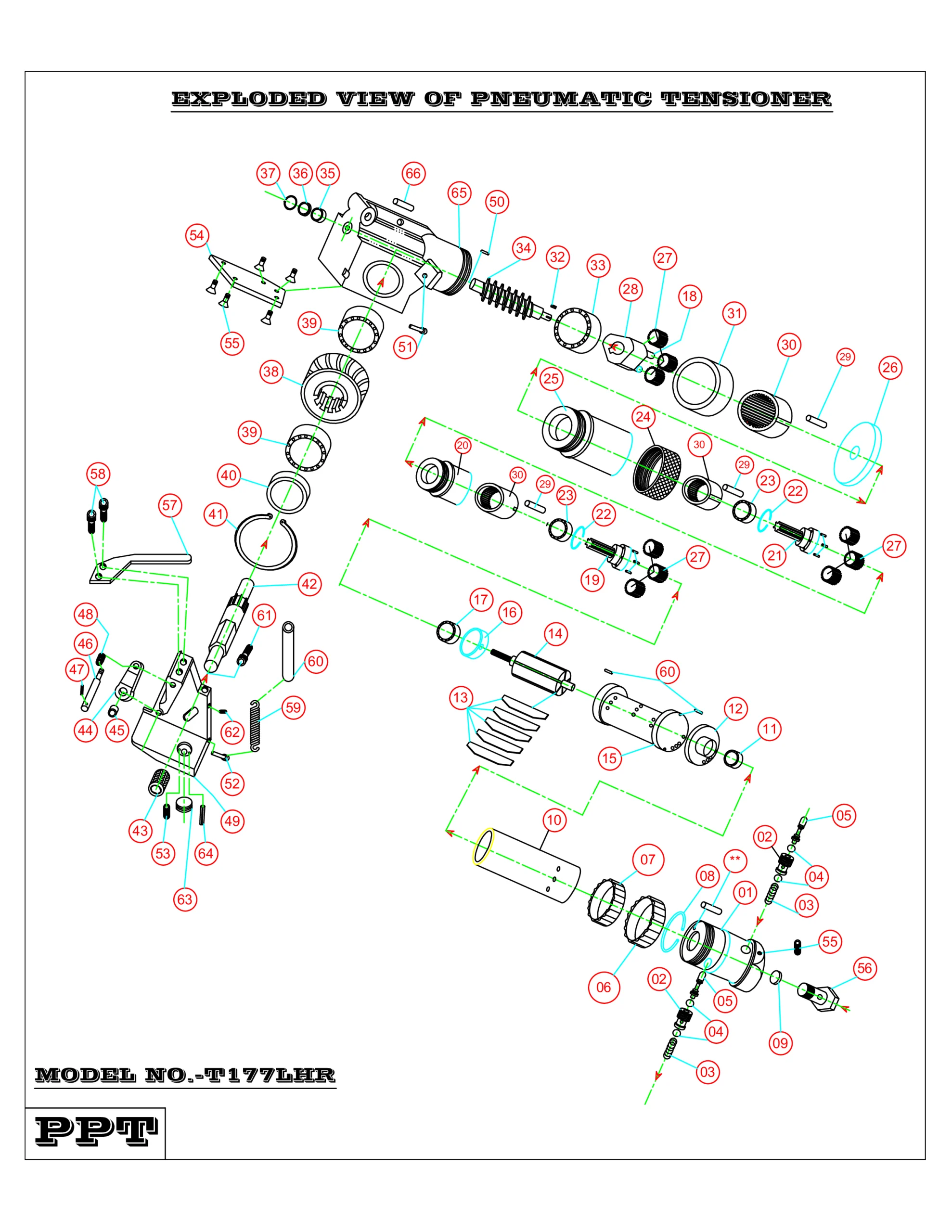
| SL.NO | ITEM NAME | QTY |
|---|---|---|
| 01 | BACK HEAD | 01 |
| 02 | VALVE BODY | 02 |
| 03 | VALVE SPRING | 02 |
| 04 | VALVE ‘O’ RING | 04 |
| 05 | VALVE POPPET | 02 |
| 06 | CONTROL RING No. 2 | 01 |
| 07 | CONTROL RING No. 1 | 01 |
| 08 | SPLIT SPRING | 01 |
| 09 | NET FITTING | 01 |
| 10 | BODY | 01 |
| 11 | BEARING NO. 1 6007Z (LLZ22) | 05 |
| 12 | END PLATE NO. 2 | 01 |
| 13 | ROTOR VANE | 05 |
| 14 | ROTOR | 01 |
| 15 | CYLINDER | 01 |
| 16 | END PLATE NO. 1 | 01 |
| 17 | BEARING NO. 2 6000ZZ | 01 |
| 18 | 1 MODULE IDLE GEAR PIN | 01 |
| 19 | GEAR BOX NO. 2 | 01 |
| 20 | BEARING HOUSING NO. 2 | 01 |
| 21 | GEAR BOX NO. 1 | 05 |
| 22 | CIRCLIP | 02 |
| 23 | BEARING 6001Z Z | 02 |
| 24 | TIGHTENING NUT | 01 |
| 25 | BEARING HOUSING NO. 1 | 01 |
| 26 | COVER PLATE | 01 |
| 27 | 1 MODULE IDLE GEAR | 09 |
| 28 | 1 MODULE PLANET HOLDER | 01 |
| 29 | LOCKING PIN | 03 |
| 30 | 1 MODULE INTERNAL GEAR | 03 |
| 31 | SPACER | 01 |
| 32 | KEY BAR | 01 |
| 33 | BEARING NO. 4 (7203B) | 01 |
| 34 | WORM SHAFT | 01 |
| 35 | BEARING NO. 5 (B 78) | 01 |
| 36 | BEARING NO. 6 (B 78) | 01 |
| 37 | CIRCLIP | 01 |
| 38 | WORM WHEEL | 01 |
| 39 | BEARING NO. 6 (EE6) | 02 |
| 40 | BEARING COVER | 01 |
| 41 | CIRCLIP | 01 |
| 42 | ROLLER SPINDLE | 01 |
| 43 | ROLLER | 01 |
| 44 | LINK ARM | 01 |
| 45 | OILET BUSH | 01 |
| 46 | SPINDLE FOR LINK ARM | 01 |
| 47 | C PIN | 01 |
| 48 | ROUND NUT | 01 |
| 49 | ROLLER FRAME | 01 |
| 50 | SPRING | 01 |
| 51 | TENSION SPRING | 01 |
| 52 | STRAP GUIDE | 01 |
| 53 | SPINDLE | 01 |
| 54 | NUT | 01 |
| 55 | HANDLE | 01 |
| 56 | SCREW | 02 |
| 57 | BOTTOM COVER | 04 |
| 58 | SCREW | 04 |
| 59 | STRAP GUIDE ADJUSTMENT BOLT | 01 |
| 60 | STRAP GUIDE ADJUSTMENT NUT | 01 |
| 61 | SPRING COVER | 01 |
| 62 | GRUB SCREW | 01 |
| 63 | PRESSURE PAD | 01 |
| 64 | C PIN | 01 |
| 65 | WORM HOUSING | 01 |
| 66 | CHECK NUT | 01 |
| 67 | STOPPER PIN | 01 |
| 68 | LOCKING CAP | 01 |
OPERATIONAL MANUAL:
- Pre-cut the strap from the coil as per required length & insert the strap in to the seal in such a way so that flat surface of the seal remains facing outside the strap.
- Apply the strap around the package and bottom strap insert through the seal. Then hold the overlap portion of the straps with your left hand.
- Pull out excess slack with your right hand.
- Hold together the handle and body of the air motor with your right hand and lift upward the air motor portion against the handle to make gap between feed wheel & lower Roller.
- Insert both the straps in the gap between feed wheel and pressure pad of the tool, at the same time push the tool forward against the seal, and release the air motor body to grip the strap.
- Turn the control ring clockwise for tensioning until proper tension is achieved.
- Seal the strap by using recommended sealer.
- Now turn the control ring anticlockwise to reverse the feed wheel movement and release the machine from the tensioned strap.
- Seal the strap by using recommended sealer.
NOTE:
- Install FRL Unit in every line where pneumatic machines are running.
MAINTENANCE:
DAILY INSPECTION:
- Perform a daily visual inspection for any signs of wear or damage.
- Check and tighten all bolts and fasteners.
- Lubricate all moving parts before operating the machine – especially the lubricating point provided in the machine.
WEEKLY INSPECTION:
- Clean the machine to prevent dust and debris build-up.
- Check and tighten all bolts and fasteners.
- Replace any worn-out components.
MONTHLY INSPECTION:
- Inspect critical components for signs of wear and replace if necessary.
- Maintain a log of all maintenance activities.
QUARTERLY INSPECTION:
- Conduct a thorough inspection of the entire system.
- Replace any worn-out components.
ANNUAL INSPECTION:
- Perform a comprehensive overhaul of the system.
- Schedule a professional inspection and servicing.
SAFETY INSTRUCTIONS:
- Before using the tool, read the operating instructions carefully.
- Wear hand gloves, safety shoe, Helmet, goggles during operation.
- When cutting the strap hold the upper portion and stand safely away from the strap.
- Do not stand in line with the strap while it is tensioned. The strap may break.
- Do not put your fingers into the Tensioner wheel area.
- Do not put your hand under the strap on the job while strap is tensioned.
- Only use equipment recommended for the strap. `T-177LHR’ are recommended only for up to 1.27 mm thick × 31.75 mm width.
Related Products