info@strappingtoolppt.com
 +91 7604 006 074

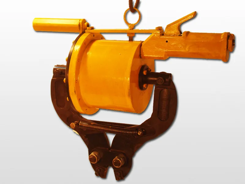
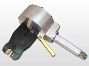
Pneumatic Bolt Cutter
Model No.: PBC-12
PPT Pneumatic Bolt Cutter – Ø12 mm Capacity, Lightweight, Compact Industrial Tool with Replaceable Inserts.
Description
The PPT Pneumatic Bolt Cutter is a powerful, air-operated tool designed for quick, safe, and efficient cutting of mild steel rods up to Ø12 mm. Featuring replaceable inserts with three cutting edges, it eliminates jaw replacement costs. Compact and lightweight at 12 kg, it delivers 2-second cutting cycles at 6 kg/cm² – 6.5 kg/cm² air pressure, ensuring durability and productivity in workshop applications.
 Download User Manual
Features:
- This powerful Pneumatic Bolt cutter is easy to operate, quick & safe in action.
- Light weight and compact design makes it suitable to use anywhere in the workshop by tool hanger or tool holding fixture for production purpose.
- Internal stop eliminates damage to the jaws during cutting operation.
Advantages:
- Changeable Insert fitted with the jaws and there are three cutting edges in one insert. Replaceable insert eliminate the need to replace the jaws when the inserts worn-out.
Specification:
- Size of Rod to Be Cut : Up to 12 mm / 0.47″ (MS) sizes varies depends upon the grade and hardness of the material.
- Working Pressure : 6.5 Kg/sq.cm. to 7.0 Kg/sq.cm.
- Weight Of The Tool : 12 Kg / 26.4 lb.
- Cutting Time : 02 sec.
| Sl.No | Size of the Rod to be cut | Required Air Pressure |
|---|---|---|
| 01 | Ø12.0 mm | 6.5 to 7.0 kg/cm² |
| 02 | Ø10.0 mm | 6.0 to 6.5 kg/cm² |
| 03 | Ø8.0 mm | 5.0 to 5.5 kg/cm² |
Note:
- Size of the Rods to be cut varies depends upon the Tensile Strength and hardness of the Material.
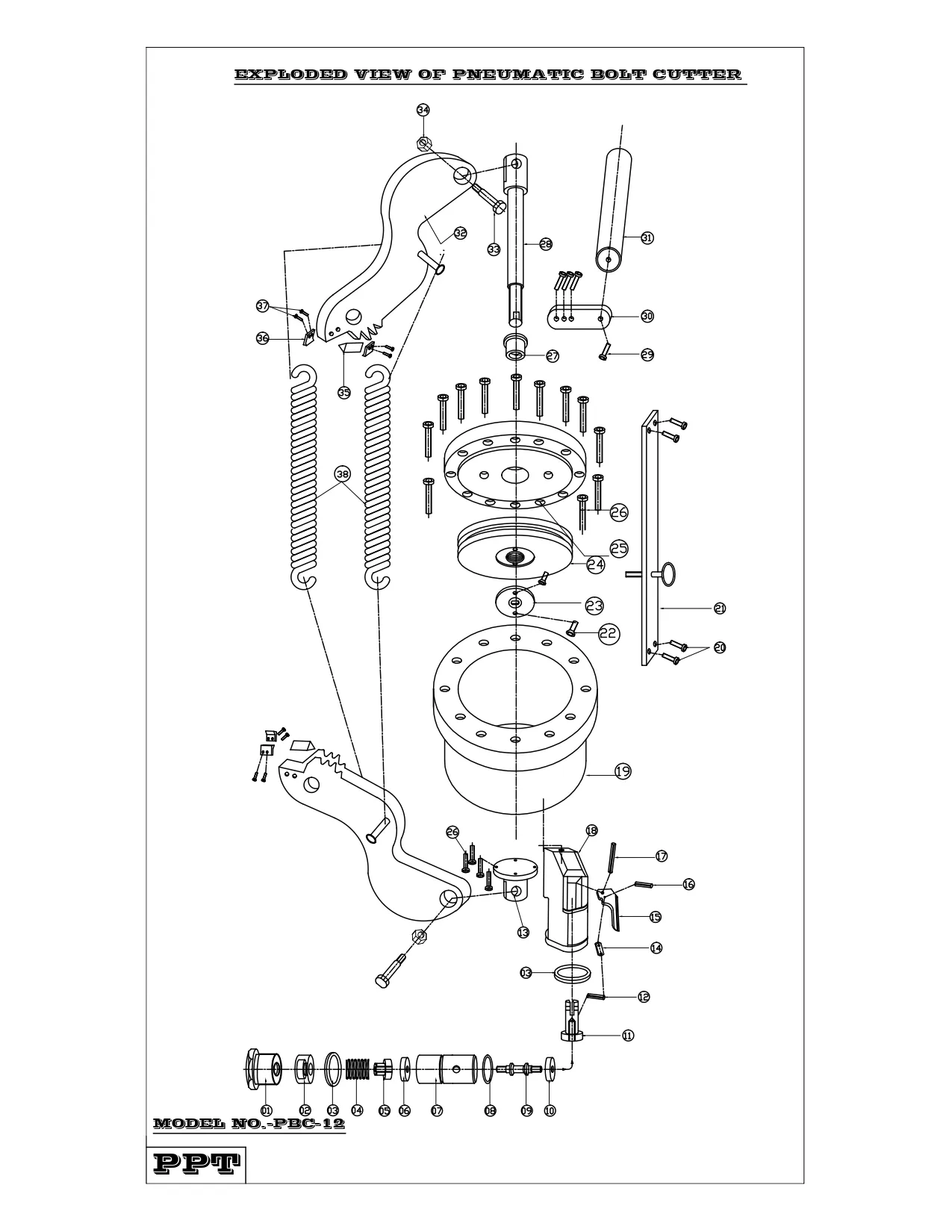
| Index No. | Part Number | Part Name | Quantity |
|---|---|---|---|
| 1 | PBC120001F | Air Inlet Nut | 1 |
| 2 | PBC120002F | Spring Cap | 1 |
| 3 | PBC120003F | Valve Body Washer | 2 |
| 4 | PBC120004B | Spring for Valve | 1 |
| 5 | PBC120005F | Washer Lock (Short) | 1 |
| 6 | PBC120006B | Valve Poppet Washer-1 | 1 |
| 7 | PBC120007F | Valve Body | 1 |
| 8 | PBC120008B | O Ring for Valve Body | 1 |
| 9 | PBC120009F | Valve Poppet | 1 |
| 10 | PBC120010B | Valve Poppet Washer-2 | 1 |
| 11 | PBC120011F | Washer Lock (Long) | 1 |
| 12 | PBC120012B | C-Pin-1 | 1 |
| 13 | PBC120013F | Jaw Holding Flange | 1 |
| 14 | PBC120014F | Trigger Link | 1 |
| 15 | PBC120015F | Trigger | 1 |
| 16 | PBC120016B | C-Pin-2 | 1 |
| 17 | PBC120017B | C-Pin-3 | 1 |
| 18 | PBC120018F | Machine Handle | 1 |
| 19 | PBC120019F | Cylinder Body | 1 |
| 20 | PBC120020B | Socketed Head Bolt-1 | 4 |
| 21 | PBC120021F | Cylinder Body & Flange Fixing Flat | 1 |
| 22 | PBC120022B | CSK Screw | 2 |
| 23 | PBC120023F | Cover Plate | 1 |
| 24 | PBC120024F | Piston | 1 |
| 25 | PBC120025F | Cylinder Flange | 1 |
| 26 | PBC120026B | Socketed Head Bolt-2 | 16 |
| 27 | PBC120027F | Bush for Piston Rod | 1 |
| 28 | PBC120028F | Piston Rod | 1 |
| 29 | PBC120029B | Socketed Head Bolt-3 | 4 |
| 30 | PBC120030F | Flat for Handle | 1 |
| 31 | PBC120031F | Pipe for Handle | 1 |
| 32 | PBC120032F | Jaw | 2 |
| 33 | PBC120033B | Jaw Holding Bolt | 2 |
| 34 | PBC120034B | Nut for Jaw Holding Bolt | 2 |
| 35 | PBC120035F | Replaceable Cutter Tip | 2 |
| 36 | PBC120036F | Cutter Tip Holding Block | 4 |
| 37 | PBC120037B | Socketed Head Bolt-4 for Tip Holding | 8 |
| 38 | PBC120038B | Tension Spring | 2 |
OPERATIONAL MANUAL:
- Connect the Pneumatic Quick disconnect socket with the pneumatic bolt cutter.
- Before connecting the pneumatic hose with Quick disconnect socket fitted with the pneumatic bolt cutter, Please check the FRL is fitted with pneumatic hose line and the hose in safe working condition.
- Check the on line air pressure at the end of the pneumatic bolt cutter.
- Moves the jaws forward and backward for some times by pressing the trigger.
- Before starting to use the tool please check the Rod Diameter and the Tensile Strength of the material is within the capability of the tool.
- Place the rod to be cut between two jaws and press the trigger. Keep cutter jaws at right angle to the rod to be cut.
NOTE:
- An AIR FILTER, REGULATOR, LUBRICATOR unit must be installed as close to the air tool as possible.
- A Quick disconnect Socket fitting must be installed at the end of the pneumatic bolt cutter.
MAINTENANCE:
DAILY INSPECTION:
- Perform a daily visual inspection for any signs of wear, damage, or leaks.
- Examine Pneumatic hoses and connections for any wear or damage.
- Check and tighten all bolts and fasteners.
- Lubricate all moving parts before operating the machine.
- Apply lubricating oil at the air inlet point and operate the trigger to allow the oil to lubricate the valve position. Carryout this practice every day at the start of work and at the end of the day.
- Clean travel area of the Moving Blade.
WEEKLY INSPECTION:
- Inspect for any air leaks.
- Clean the machine to prevent dust and debris build-up.
MONTHLY INSPECTION:
- Inspect critical components for signs of wear and replace if necessary.
- Maintain a log of all maintenance activities.
ANNUAL INSPECTION:
- Perform a comprehensive overhaul of the pneumatic bolt cutter.
- Schedule a professional inspection and servicing.
SAFETY INSTRUCTIONS:
- Before using the pneumatic bolt cutter, read the operating instructions carefully.
- Must Operated by a Trained Personnel equipped with appropriate Personal Protective Equipment (PPE).
- This Model is Suitable for certain Size of Rod and Tensile Strength. Do not ever try to cut Oversize Rod and Greater Tensile Strength.
- Ensure the Rod is placed securely between the Jaws.
- While the tool is not in use, turn off the air Supply.
- Before the Operation make sure to keep hands and body clear of the Jaws.
- See that nobody is standing on the other end of the rod, because depending on the tensile strength of the material and flow rate of air, the parted portion of the rod may shoot out at high speed causing injury.
- During the Operation Don’t let any Untrained and Unauthorized personnel near the machine.
Related Products